Understanding Loudspeaker Distortion
When you mention distortion and audio in the same sentence, it generally invokes thoughts of electric guitars or speakers cranked so loud the bass gets fuzzy. But distortion in speakers is really a pretty in-depth topic, not only because there are several different types of distortion that can occur, but because the audibility of distortion in a loudspeaker can often become a point of contention. Today I wanted to cover a little bit about the three main types of distortion generated in loudspeakers, what they mean, and how to interpret distortion results. There are two types of distortion that will be discussed here – linear distortion and non-linear distortion (harmonic and intermodulation distortion).

Linear Distortion
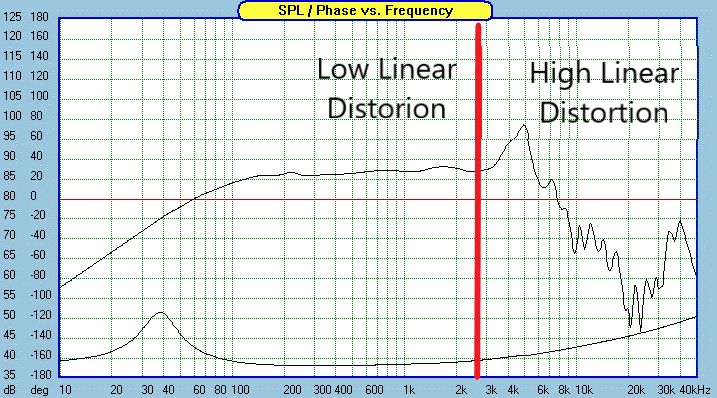
The first and most prevalent type of distortion is linear distortion. Linear distortion is distortion in the frequency response. When we perform a sinewave sweep from 20 Hz to 20 kHz, the input signal is actually providing the same driver level at all frequencies in the sweep. This means that in an ideal world, the speaker would output a flat line from 20 Hz to 20 kHz, or in effect, it would reproduce the input signal exactly. However, in the real world this doesn’t happen for a variety of reasons, especially when we look at individual drivers. Deviations from the ideal flat line are considered linear distortion. This article isn’t going to focus on the argument of whether or not flat frequency response is best. That is outside the scope today, but what is definitive is that the more a speaker deviates from the ideal straight line response, the more linear distortion it has.
Causes of linear distortion are numerous and many of them are unavoidable. For instance, physics dictates that a tweeter can’t both extend to very high frequencies and also play to very low frequencies at the same time. Cone or dome geometries can change resonance modes or cancellations, which will affect linear distortion. High inductance on a woofer causes early roll-off of top end frequencies. Linear distortion will always be present to some degree. What we want is to minimize it as much as possible. We do this through good motor design and cone/dome design that make the driver operate more linearly and pistonic throughout its operating range.
Harmonic Distortion
Harmonic distortion is the second main type of distortion in loudspeakers. Harmonic distortion happens when a fundamental tone or note is played at one frequency and multiples, or harmonics, of that note are reproduced at higher frequencies without actually being an input to the speaker. For example, we might input a 200 Hz test tone, which is the fundamental, but the output will show a 200 Hz tone, a 400 Hz tone, and a 600 Hz tone. These harmonics are labeled are labeled 2nd order, 3rd order, 4th order, and so on. In this example, the 2nd order would be the 400 Hz and the 3rd order the 600 Hz tones.
Harmonic distortion is measured in dB and compared to the level of the original signal to convert to a percentage, which is usually displayed as THD (total harmonic distortion) or THD+N (total harmonic distortion plus noise). However, each order of harmonic makes up a portion of that percentage and most would agree that odd order distortion (3rd, 5th, etc) is more audible than even order so knowing the breakdown of each component is important. Seeing the individual levels of each component can also tell you something about the design of the driver. For instance, drivers that have basic motor designs will generally have rising 3rd order distortion the higher in frequency you go while advanced motor designs will generally have even or even declining 3rd order. Other things outside of motor design can affect the harmonics as well. Metal cone drivers can have cone breakup that causes ringing and produce related distortion spikes in the harmonic distortion. That’s not to say that any of these mean a driver is unusable. Much of that is up to how well a designer understands and compensates for issues identified in the measurements with the crossover design.
Harmonic distortion is typically said to be inaudible below 1% THD. I would generally agree with that but with a couple of caveats. Below 1%, you don’t hear it as a distortion of the signal anymore. However, what I do find is that drivers with lower distortion tend to sound “cleaner” and often might be described by some people as more sterile or less exciting. By cleaner, I mean that I hear more low-level detail like subtle echoes or long decays of notes that get masked in the higher distortion drivers. Second, I would also say that 1% distortion due to 3rd order is likely going to be much more noticeable than 1% second order. That’s another reason why I think that having the actual component breakdown of distortion products is important.
Intermodulation Distortion
Intermodulation distortion (or IMD) is the third main type of distortion and arguably the worst of the three. IMD occurs when two tones are played simultaneously (which unless you listen to pure test tones is always occurring in music) and their interaction produces other tones that are unrelated to the original signal. While harmonic distortion is always multiples of the original, IMD is not a multiple. For instance, with IMD I could play that 200 Hz test tone from the earlier example with a 1000 Hz test tone and get an additional 800 Hz tone. This would be in addition any harmonic distortion from the two tones on their own. You can probably tell why this would be much more audible. A new tone that isn’t musically related to the original notes being generated can make things sound unrealistic at best and awful at worst.

IMD isn’t often talked about a lot because it is more challenging to measure. Measuring harmonic distortion is as simple as conducting a long wave sine sweep and takes about 10 seconds. IMD is basically impossible to measure in the same absolute terms as total harmonic distortion is because you would have to measure every combination of notes at every frequency and new IMD products can be created by doing 3 test tones instead of two. So instead, one might measure only a set amount of tone combinations for all your drivers. This will give you a good idea of relative performance.
Distortion Comparisons
It’s easy to want to compare distortion measurements you find on the internet with each other, but you should have caution doing so in most instances. There are several things that can affect distortion measurements rather drastically, so doing direct comparisons from two different sources can end up being an apples to oranges comparison.
Different measuring distances, SPL levels, gear, and background noise can all affect distortion levels. A measurement taken at 90 dB at 10 centimeters and one taken at 1 meter are not the same in terms of the stress they put on a driver and cannot be compared directly. The 10 cm measurement would be expected to show significantly lower distortion. It’s important to know the measurement conditions for any distortion measurement.
Generally I would say that distortion measurements are only directly comparable when conducted by the same person or facility on the same test setup under the same conditions. When comparing between different sources for measurements, the best you can get is a directional indication of the driver’s performance.
What we measure
At CSS, we typically only measure linear and harmonic distortion ourselves. IMD becomes too time consuming to take enough measurements to be meaningful, and while it does not necessarily have a 100% correlation in absolute terms, the same things that make a driver have good harmonic distortion typically improve IMD as well. We outsource Klippel testing of our drivers to further validate performance under high excursion.